
Why Engineering Drawings Matter in Precision Metal Manufacturing
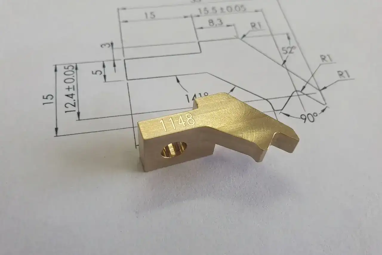
An engineering drawing is more than a picture of a component. It is the technical reference used to communicate what needs to be manufactured, which dimensions are important, what material is required and which characteristics need to be controlled.
For precision metal components, a clear drawing can make the difference between producing a part that merely looks correct and producing one that actually fits and performs within the intended assembly.
What Information Does an Engineering Drawing Provide?
A manufacturing drawing can contain dimensions, tolerances, material specifications, threads, surface requirements, geometric information, notes and other details needed to define the component.
Each piece of information has a purpose. The nominal dimension describes the intended size, while the tolerance defines how much variation is acceptable. Notes may specify material, finishing, inspection or other requirements that cannot be communicated through dimensions alone.
Why Dimensions Alone Are Not Enough
Consider a component with several holes. Knowing the diameter of each hole does not necessarily tell a manufacturer where those holes need to be located relative to one another. Similarly, knowing the outside diameter of a shaft does not fully define its relationship with another feature.
Feature position, orientation and relationship can be just as important as individual dimensions. This is why drawings need to be interpreted as a complete engineering document rather than as a collection of isolated numbers.
The Role of Tolerances
Tolerances establish the acceptable manufacturing range for a dimension. Without a defined tolerance, different people may interpret the same nominal dimension differently.
- Dimensional tolerance: Controls the permitted variation in size.
- Geometric requirements: Help control relationships such as position, orientation or form when specified.
- Surface requirements: Define characteristics that may affect friction, appearance or assembly.
- Thread specifications: Define the required thread form and dimensional requirements.
The tighter the requirement, the more carefully the manufacturing and inspection process generally needs to be controlled. However, tighter is not automatically better. Tolerances should reflect the actual functional requirement of the assembly.
Material Specifications Influence Manufacturing
The material written on a drawing is part of the component specification. Changing the material can change machining behaviour, strength, conductivity, corrosion resistance, weight and other properties relevant to the application.
For example, brass, copper and aluminium can have very different machining characteristics and functional properties. Stainless steel and mild steel also have their own manufacturing considerations. Material selection should therefore be treated as an engineering decision, not simply a purchasing decision.
How a Drawing Guides the Manufacturing Process
Step 1: Review the Complete Drawing
The first step is to understand the component as a whole. Dimensions, tolerances, material, threads, surface requirements and notes should be reviewed together.
Step 2: Identify Critical Features
Not every feature has the same functional importance. Critical diameters, mating surfaces, hole positions, threads or other application-specific characteristics should be identified before production planning begins.
Step 3: Select the Manufacturing Route
The component geometry and material help determine whether turning, milling, drilling or a combination of operations is appropriate. The selected route should allow the required characteristics to be produced consistently.
Step 4: Plan Inspection
Inspection should focus on the requirements that define acceptance. A good inspection plan connects measurement points directly to the drawing so that production and quality teams are working from the same specification.
Common Drawing Problems That Can Cause Manufacturing Delays
Manufacturing problems do not always originate on the shop floor. Ambiguous drawings can also create delays, questions and rework.
- Missing or unclear critical dimensions
- Unspecified material or material grade
- Unclear thread requirements
- Conflicting dimensions or notes
- Tolerances that do not match the functional requirement
- Missing information about surface or finishing requirements
When a requirement is unclear, clarification before production is usually better than making assumptions and discovering the problem after machining.
Why Drawing Interpretation Is a Manufacturing Skill
Two components can have similar external shapes but require completely different manufacturing approaches because their tolerances, materials or functional requirements are different. Reading the drawing correctly helps the manufacturing team understand what actually matters.
This is particularly important for custom and repeat production. Once the engineering requirement is understood, the process can be planned around the features that need the greatest control.
Engineering Drawings and Quality Control
The drawing provides measurable acceptance criteria for inspection. Instead of judging a component only by appearance, quality personnel can compare the manufactured characteristics against documented requirements.
This supports a more consistent quality process. DIPAK SALES is certified to ISO 9001:2015 for the manufacture of precision metal components, providing a documented quality-management framework around its certified manufacturing scope.
How Clear Drawings Improve Communication
A well-prepared drawing creates a common technical reference for engineering, manufacturing, quality and the customer. It reduces the need to explain every requirement through separate conversations and helps keep the production target consistent.
For ongoing production, the drawing also becomes an important reference when reviewing process changes, inspection results or future production requirements.
Frequently Asked Questions
Why are engineering drawings important in manufacturing?
They communicate the dimensions, tolerances, material and other technical requirements needed to manufacture and inspect a component correctly.
What is the difference between a dimension and a tolerance?
A dimension states the intended size or location, while a tolerance defines the acceptable variation around that requirement.
Can unclear drawings affect production?
Yes. Missing or ambiguous information can lead to clarification requests, incorrect assumptions, rework or delays. Clear specifications help reduce these risks.
Conclusion
Engineering drawings provide the foundation for controlled precision manufacturing. When dimensions, tolerances, materials and technical notes are clearly understood, manufacturers can select the right process and establish meaningful inspection criteria. The result is a stronger connection between engineering intent and the component that comes off the production line.


